
Figure 3.1: Schematic diagram of Screen Space Fluid Rendering
This chapter introduces Screen Space Fluid Rendering by Deferred Shading as one of the particle rendering methods .
Traditionally, the Martin Cubes method is used to render fluid-like continuums, but it is relatively computationally intensive and not suitable for detailed drawing in real-time applications. Therefore, a method called Screen Space Fluid Rendering was devised as a method for drawing particle-based fluids at high speed .
Figure 3.1: Schematic diagram of Screen Space Fluid Rendering
This creates a surface from the depth of the surface of the particles in the screen space visible to the camera, as shown in Figure 3.1.
A technique called Deferred Rendering is used to generate this surface geometry .
2-dimensional screen space (screen space) in the shading (shadow calculation) is a technology to perform. For the sake of distinction, the traditional type of technique is called Forward Rendering .
Figure 3.2 outlines the traditional Forward Rendering and Deferred Rendering rendering pipelines.
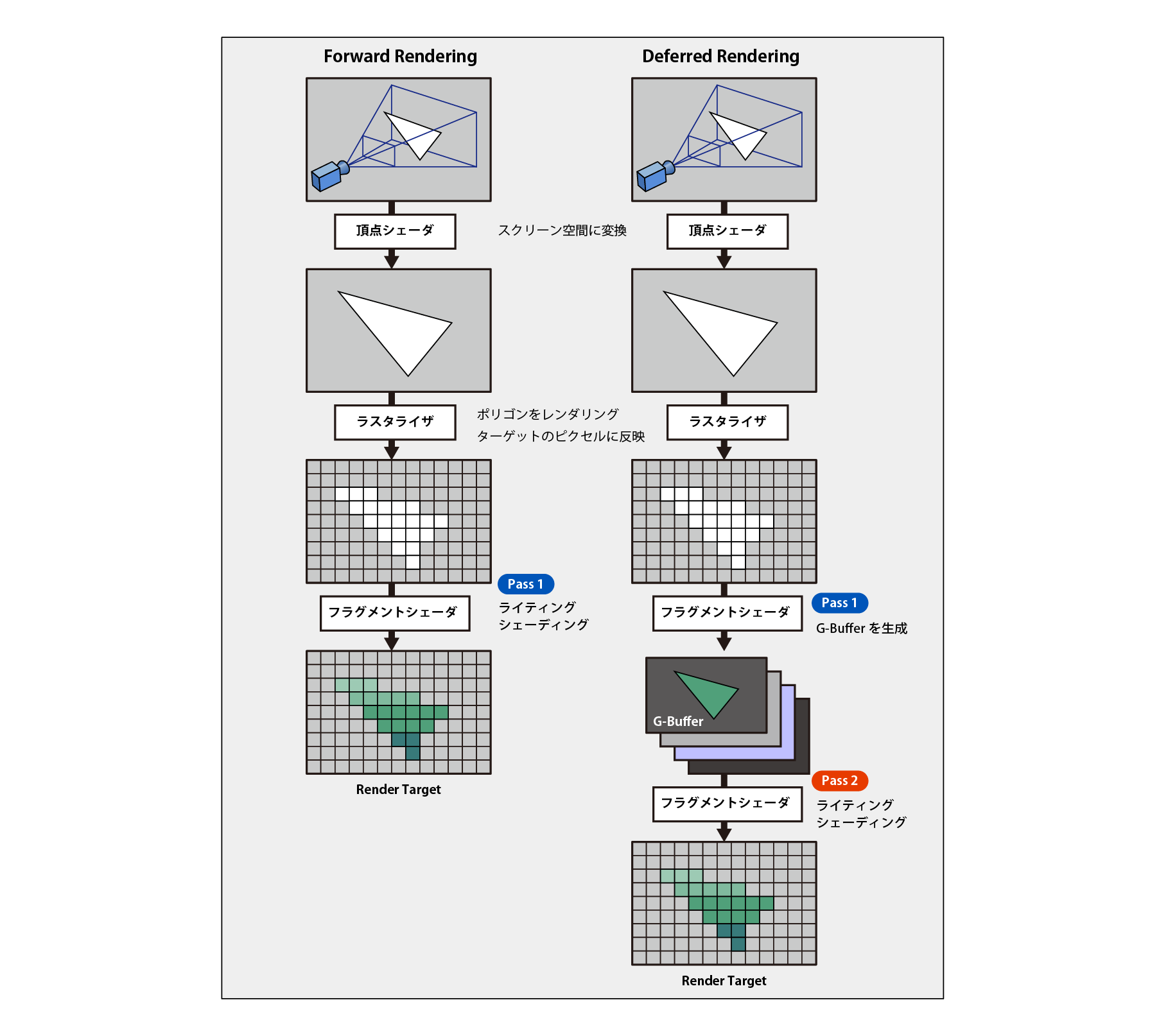
Figure 3.2: Comparison of Foward Rendering and Deferred Rendering pipelines
In the case of Forward Rendering , lighting and shading processing are performed in the first pass of the shader, but in Deferred Rendering , 2D image information such as normal , position , depth , diffuse color required for shading is generated, and G-Buffer Store in a buffer called. In the second pass, that information is used to perform lighting and shading to obtain the final rendering result. This delays the actual rendering to the second pass (and beyond) , hence the name "Deferred" Rendering .
The advantage of Deferred Rendering is
The downside is
There are some restrictions such as trade-offs, so it is necessary to consider them before making a decision.
Deferred Rendering has the following usage conditions, and this sample program may not work depending on the environment. ..
Also, Deferred Rendering is not supported when using Orthographic projection , and Forward Rendering is used when the camera's projection mode is set to Orthographic .
Information about (2D texture) in screen space, such as normals , positions , and diffuse colors used for shading and lining calculations, is called G-Buffer . In the G-Buffer path of Unity's rendering pipeline , each object is rendered once and rendered into a G-Buffer texture , generating the following information by default:
Form 3.1:
| render target | format | data type |
|---|---|---|
| RT0 | ARGB32 | Diffuse color (RGB), Occulusion (A) |
| RT1 | ARGB32 | Specular color (RGB), Roughness (A) |
| RT2 | ARGB2101010 | World space normal (RGB) |
| RT3 | ARGB2101010 | Emission + (Ambient + Reflections + Lightmaps) |
| Z-buffer | Depth + Stencil |
These G-Buffer textures are set as global properties and can be retrieved within the shader.
Table 3.2:
| shader property name | data type |
|---|---|
| _CameraGBufferTexture0 | Diffuse color (RGB), occulusion (A) |
| _CameraGBufferTexture1 | Specular color (RGB) |
| _CameraGBufferTexture2 | World space normal (RGB) |
| _CameraGBufferTexture3 | Emission + (Ambient + Reflections + Lightmaps) |
| _CameraDepthTexture | Depth + Stencil |
If you open Assets / ScreenSpaceFluidRendering / Scenes / ShowGBufferTest in the sample code, you can see how this G-Buffer is acquired and displayed on the screen.

Figure 3.3: G-Buffer generated by default
The sample program introduced in this chapter uses Unity's API called CommandBuffer .
The drawing process itself is not performed in the method written in the script executed by the CPU . Instead, it is added to the GPU 's understandable list of rendering commands , called the graphics command buffer, and the generated command buffer is read directly by the GPU and executed to actually draw the object.
Rendering commands provided by Unity are , for example, methods such as Graphics.DrawMesh () and Graphics.DrawProcedural () .
Of Unity of API CommandBuffer By using, Unity of the rendering pipeline to a specific point in the command buffer (a list of the rendering commands) by inserting a, Unity of the rendering pipeline can be extended to.
You can see some sample projects using CommandBuffer here.
https://docs.unity3d.com/ja/current/Manual/GraphicsCommandBuffers.html
In the following, we will briefly explain the 3DCG graphics pipeline and coordinate system to understand the contents of the calculations performed on the screen space.
When considering a three-dimensional position vector (x, y, z), it is sometimes treated as a four-dimensional one such as (x, y, z, w), which is called Homogeneous Coordinates. .. By thinking in four dimensions in this way, you can effectively multiply 4x4 Matrix. The calculation of the coordinate transformation is basically done by multiplying the 4x4 Matrix, so the position vector is expressed in 4 dimensions like this.
The conversion between homogeneous coordinates and non-homogeneous coordinates is done in this way. (x / w, y / w, z / w, 1) = (x, y, z, w)
The coordinate system around which the object itself is central.
World Space is a coordinate system that shows how multiple objects are spatially related in a scene, centered on the scene. The World Space is transformed from the Object Space by a Modeling Transform that moves, rotates, and scales the object .
Eye Space is a coordinate system centered on the drawing camera and with its viewpoint as the origin. Orientation on the position and the camera of the camera, was to define the information, such as a camera focus direction of the orientation of the View Matrix According to the View Transform by making a World Space will be converted from.
Clip Space , the above View Matrix other parameters of the camera defined by and defines a field of view (FOV) · aspect ratio · near clip · _far clip Projection Matrix and View Space coordinate system obtained by converting multiplying the is. This transformation is called the Projection Transform , which clips the space drawn by the camera.
Coordinate value obtained by Clip Space xyz By dividing each element by w, the range is -1 <= x <= 1, -1 <= y <= 1, 0 <= z <= 1. All position coordinates are normalized. The coordinate system obtained by this is called Normalized Device Coordinates (NDC) . This transformation is called Persepective Devide, and the objects in the foreground are drawn larger and the ones in the back are drawn smaller.
A coordinate system in which the normalized values obtained by Normalized Device Coordinates are converted to match the screen resolution. In the case of Direct3D, the origin is the upper left.
Deferred Rendering calculates based on the image in this screen space, but if necessary, it calculates and uses the information of any coordinate system by multiplying it by the inverse matrix of each transformation, so this rendering pipeline is used. It's important to understand.
Figure 3.3 illustrates the relationship between the 3DCG graphics pipeline, the coordinate system, and coordinate transformation.

Figure 3.4: Coordinate system, flow of coordinate transformation
Of the sample code
Assets/ScreenSpaceFluidRendering/Scenes/ScreenSpaceFluidRendering
Please open the scene.
The general algorithm for Screen Space Fluid Rendering is as follows.
* In this sample code, even the creation of surface geometry is performed. We do not perform transparent expressions.
Table 3.3:
| Script name | function |
|---|---|
| ScreenSpaceFluidRenderer.cs | Main script |
| RenderParticleDepth.shader | Find the depth of the particle's screen space |
| BilateralFilterBlur.shader | Blur effect that attenuates with depth |
| CalcNormal.shader | Find the normal from the depth information of the screen space |
| RenderGBuffer.shader | Write depth, normals, color information, etc. to G-Buffer |
ScreenSpaceFluidRendering.cs of OnWillRenderObject Within the function, CommandBuffer to create a, at any point of the camera of rendering path CommandBuffer make the process of registering.
Below is an excerpt of the code
ScreenSpaceFluidRendering.cs
// Called when the attached mesh renderer is in the camera
void OnWillRenderObject ()
{
  // If it is not active, release it and do nothing after that
  var act = gameObject.activeInHierarchy && enabled;
  if (!act)
  {
    CleanUp();
    return;
  }
  // If there is no camera currently rendering, do nothing after that
  var cam = Camera.current;
  if (!cam)
  {
    return;
  }

  // For the camera currently rendering
  // If CommandBuffer is not attached
  if (!_cameras.ContainsKey(cam))
  {
    // Create Command Buffer information
    var buf = new CmdBufferInfo ();
    buf.pass   = CameraEvent.BeforeGBuffer;
    buf.buffer = new CommandBuffer();
    buf.name = "Screen Space Fluid Renderer";
    // In the path on the camera's rendering pipeline before the G-Buffer was generated,
    // Add the created CommandBuffer
    cam.AddCommandBuffer(buf.pass, buf.buffer);

    // Add a camera to the list that manages cameras with CommandBuffer added
    _cameras.Add(cam, buf);
  }
The Camera.AddCommandBuffer (CameraEvent evt, Rendering.CommandBuffer buffer) method adds a command buffer to the camera that runs at any path . Here, CameraEvent.BeforeGBuffer in immediately before the G-Buffer is generated and specifies the location of where any command buffer by inserting the, you can generate a calculated geometry on the screen space. The added command buffer is deleted by using the RemoveCommandBuffer method when the application is executed or the object is disabled . The process of deleting the command buffer from the camera is implemented in the Cleanup function.
Then, CommandBuffer to the rendering command will continue to register a. At that time, at the beginning of frame update, delete all buffer commands by CommandBuffer.Clear method.
Generates a point sprite based on the data of the vertices of a given particle and calculates the depth texture in that screen space .
The code is excerpted below.
ScreenSpaceFluidRendering.cs
// --------------------------------------------------------------------
// 1. Draw particles as point sprites to get depth and color data
// --------------------------------------------------------------------
// Get the shader property ID of the depth buffer
int depthBufferId = Shader.PropertyToID("_DepthBuffer");
// Get a temporary RenderTexture
buf.GetTemporaryRT (depthBufferId, -1, -1, 24,
  FilterMode.Point, RenderTextureFormat.RFloat);

// Specify color buffer and depth buffer as render targets
buf.SetRenderTarget
(
  new RenderTargetIdentifier(depthBufferId),  // デプス
  new RenderTargetIdentifier (depthBufferId) // For depth writing
);
// Clear color buffer and depth buffer
buf.ClearRenderTarget(true, true, Color.clear);

// Set the particle size
_renderParticleDepthMaterial.SetFloat ("_ParticleSize", _particleSize);
// Set particle data (ComputeBuffer)
_renderParticleDepthMaterial.SetBuffer("_ParticleDataBuffer",
_particleControllerScript.GetParticleDataBuffer());

// Draw particles as point sprites to get a depth image
buf.DrawProcedural
(
  Matrix4x4.identity,
  _renderParticleDepthMaterial,
  0,
  MeshTopology.Points,
  _particleControllerScript.GetMaxParticleNum()
);
RenderParticleDepth.shader
// --------------------------------------------------------------------
// Vertex Shader
// --------------------------------------------------------------------
v2g vert(uint id : SV_VertexID)
{
  v2g or = (v2g) 0;
  FluidParticle fp = _ParticleDataBuffer[id];
  o.position = float4(fp.position, 1.0);
  return o;
}

// --------------------------------------------------------------------
// Geometry Shader
// --------------------------------------------------------------------
// Position of each vertex of the point sprite
static const float3 g_positions[4] =
{
  float3(-1, 1, 0),
  float3( 1, 1, 0),
  float3(-1,-1, 0),
  float3( 1,-1, 0),
};
// UV coordinates of each vertex
static const float2 g_texcoords[4] =
{
  float2(0, 1),
  float2(1, 1),
  float2(0, 0),
  float2(1, 0),
};

[maxvertexcount(4)]
void geom(point v2g In[1], inout TriangleStream<g2f> SpriteStream)
{
  g2f o = (g2f) 0;
  // Position of the center vertex of the point sprite
  float3 vertpos = In[0].position.xyz;
  // 4 point sprites
  [unroll]
  for (int i = 0; i < 4; i++)
  {
    // Find and substitute the position of the point sprite in the clip coordinate system
    float3 pos = g_positions[i] * _ParticleSize;
    pos = mul(unity_CameraToWorld, pos) + vertpos;
    o.position = UnityObjectToClipPos(float4(pos, 1.0));
    // Substitute the UV coordinates of the point sprite vertices
    o.uv       = g_texcoords[i];
    // Find and substitute the position of the point sprite in the viewpoint coordinate system
    o.vpos     = UnityObjectToViewPos(float4(pos, 1.0)).xyz * float3(1, 1, 1);
    // Substitute the size of the point sprite
    o.size     = _ParticleSize;

    SpriteStream.Append(o);
  }
  SpriteStream.RestartStrip();
}

// --------------------------------------------------------------------
// Fragment Shader
// --------------------------------------------------------------------
struct fragmentOut
{
  float  depthBuffer  : SV_Target0;
  float  depthStencil : SV_Depth;
};

fragmentOut frag(g2f i)
{
  // Calculate normal
  float3 N = (float3) 0;
  N.xy = i.uv.xy * 2.0 - 1.0;
  float radius_sq = dot(N.xy, N.xy);
  if (radius_sq > 1.0) discard;
  N.z = sqrt(1.0 - radius_sq);

  // Pixel position in clip space
  float4 pixelPos     = float4(i.vpos.xyz + N * i.size, 1.0);
  float4 clipSpacePos = mul(UNITY_MATRIX_P, pixelPos);
  // depth
  float depth = clipSpacePos.z / clipSpacePos.w; // normalization

  fragmentOut o = (fragmentOut) 0;
  o.depthBuffer  = depth;
  o.depthStencil = depth;

  return o;
}
The C # script first generates a temporary RenderTexture for calculations in screen space . In the command buffer, use the CommandBuffer.GetTemporaryRT method to create temporary RenderTexture data and use it. In the first argument of the GetTemporaryRT method, pass the unique ID of the shader property of the buffer you want to create . In shader unique ID and is, in order to access the properties of the shader that is generated each time the game scene of Unity is executed int type unique ID in, Shader.PropertyToID the method property name can be generated by passing the I can. (Since this unique ID is different in game scenes where the execution timing is different, its value cannot be retained or shared with other applications over the network.)
The second and third arguments of the GetTemporaryRT method specify the resolution. If -1 is specified, the resolution (Camera pixel width, height) of the camera currently rendering in the game scene will be passed.
The fourth argument specifies the number of bits in the depth buffer. In _DepthBuffer , we also want to write the depth + stencil value, so specify a value of 0 or more.
The resulting RenderTexture is, CommandBuffer.SetRenderTarget in the method, the render target specified, ClearRenderTarget in the method, leave the clear. If this is not done, it will be overwritten every frame and will not be drawn properly.
The CommandBuffer.DrawProcedural method draws the particle data and calculates the color and depth textures in screen space . The figure below shows this calculation.
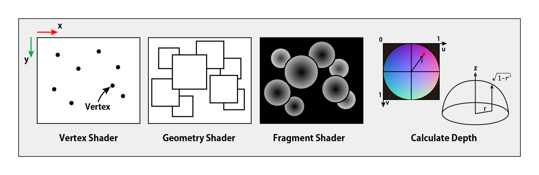
Figure 3.5: Depth image calculation
The Vertex shader and Geometry shader generate point sprites that billboard in the viewpoint direction from the given particle data . The Fragment shader calculates the hemispherical normal from the UV coordinates of the point sprite and uses this to get a depth image in screen space .

Figure 3.6: Depth image
By applying a blur effect to smooth the obtained depth image , it is possible to draw the image as if it is connected by blurring the boundary with adjacent particles. Here, a filter is used so that the offset amount of the blur effect is attenuated according to the depth.
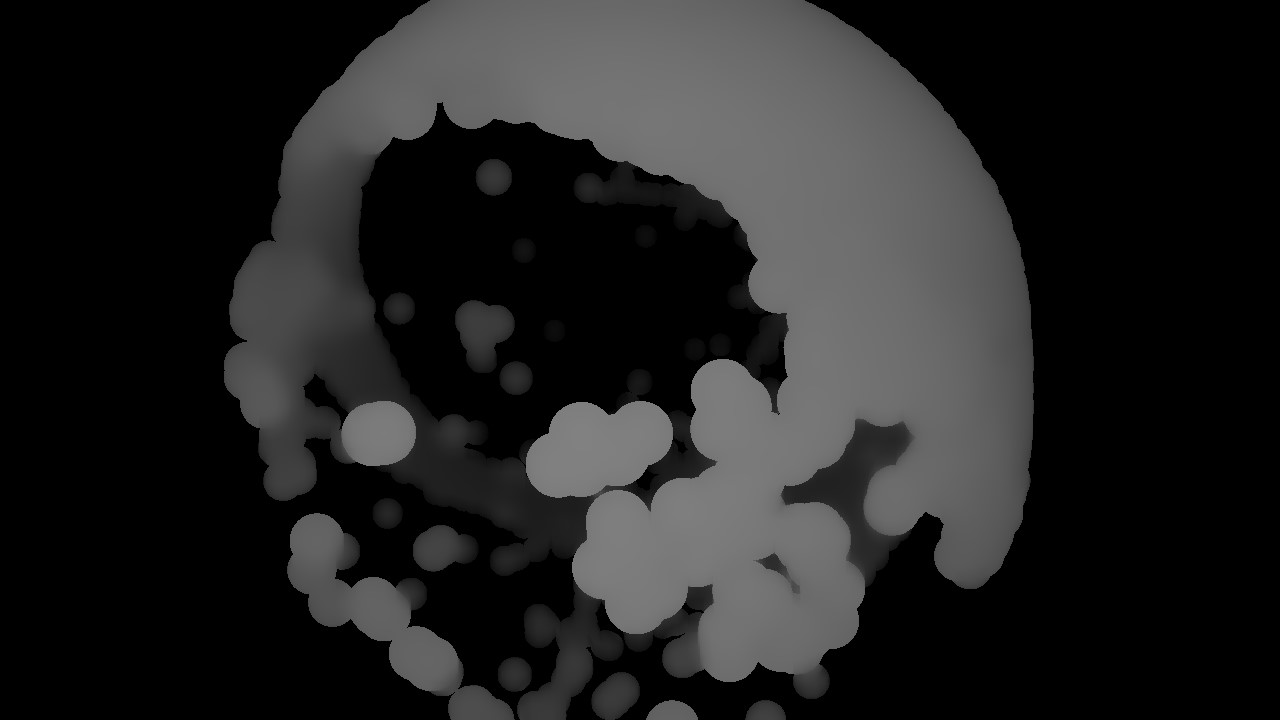
Figure 3.7: Blurred depth image
Calculate the normal from the blurred depth image . The normal is calculated by performing partial differentiation in the X and Y directions .

Figure 3.8: Normal calculation
Below is an excerpt of the code
CalcNormal.shader
// --------------------------------------------------------------------
// Fragment Shader
// --------------------------------------------------------------------
// Find the position in the viewpoint coordinate system from the UV of the screen
float3 uvToEye(float2 uv, float z)
{
  float2 xyPos = uv * 2.0 - 1.0;
  // Position in the clip coordinate system
  float4 clipPos = float4(xyPos.xy, z, 1.0);
  // Position in the viewpoint coordinate system
  float4 viewPos = mul(unity_CameraInvProjection, clipPos);
  // normalization
  viewPos.xyz = viewPos.xyz / viewPos.w;

  return viewPos.xyz;
}

// Get the depth value from the depth buffer
float sampleDepth(float2 uv)
{
#if UNITY_REVERSED_Z
  return 1.0 - tex2D(_DepthBuffer, uv).r;
#else
  return tex2D(_DepthBuffer, uv).r;
#endif
}

// Get the position in the viewpoint coordinate system
float3 getEyePos(float2 uv)
{
  return uvToEye(uv, sampleDepth(uv));
}

float4 frag(v2f_img i) : SV_Target
{
  // Convert screen coordinates to texture UV coordinates
  float2 uv = i.uv.xy;
  // get depth
  float depth = tex2D(_DepthBuffer, uv);

  // Discard pixels if depth is not written
#if UNITY_REVERSED_Z
  if (Linear01Depth(depth) > 1.0 - 1e-3)
    discard;
#else
  if (Linear01Depth(depth) < 1e-3)
    discard;
#endif
  // Store texel size
  float2 ts = _DepthBuffer_TexelSize.xy;

  // Find the position of the viewpoint coordinate system (as seen from the camera) from the uv coordinates of the screen
  float3 posEye = getEyePos(uv);

  // Partial differential with respect to x
  float3 ddx  = getEyePos(uv + float2(ts.x, 0.0)) - posEye;
  float3 ddx2 = posEye - getEyePos(uv - float2(ts.x, 0.0));
  ddx = abs(ddx.z) > abs(ddx2.z) ? ddx2 : ddx;

  // Partial differential with respect to y
  float3 ddy = getEyePos(uv + float2(0.0, ts.y)) - posEye;
  float3 ddy2 = posEye - getEyePos(uv - float2(0.0, ts.y));
  Dy = abs (Dy.z)> abs (Dy2.z)? dy2: should;

  // Find the normal orthogonal to the vector found above from the cross product
  float3 N = normalize(cross(ddx, ddy));

  // Change the normal in relation to the camera position
  float4x4 vm = _ViewMatrix;
  N = normalize(mul(vm, float4(N, 0.0)));

  // Convert (-1.0 to 1.0) to (0.0 to 1.0)
  float4 col = float4(N * 0.5 + 0.5, 1.0);

  return col;
}
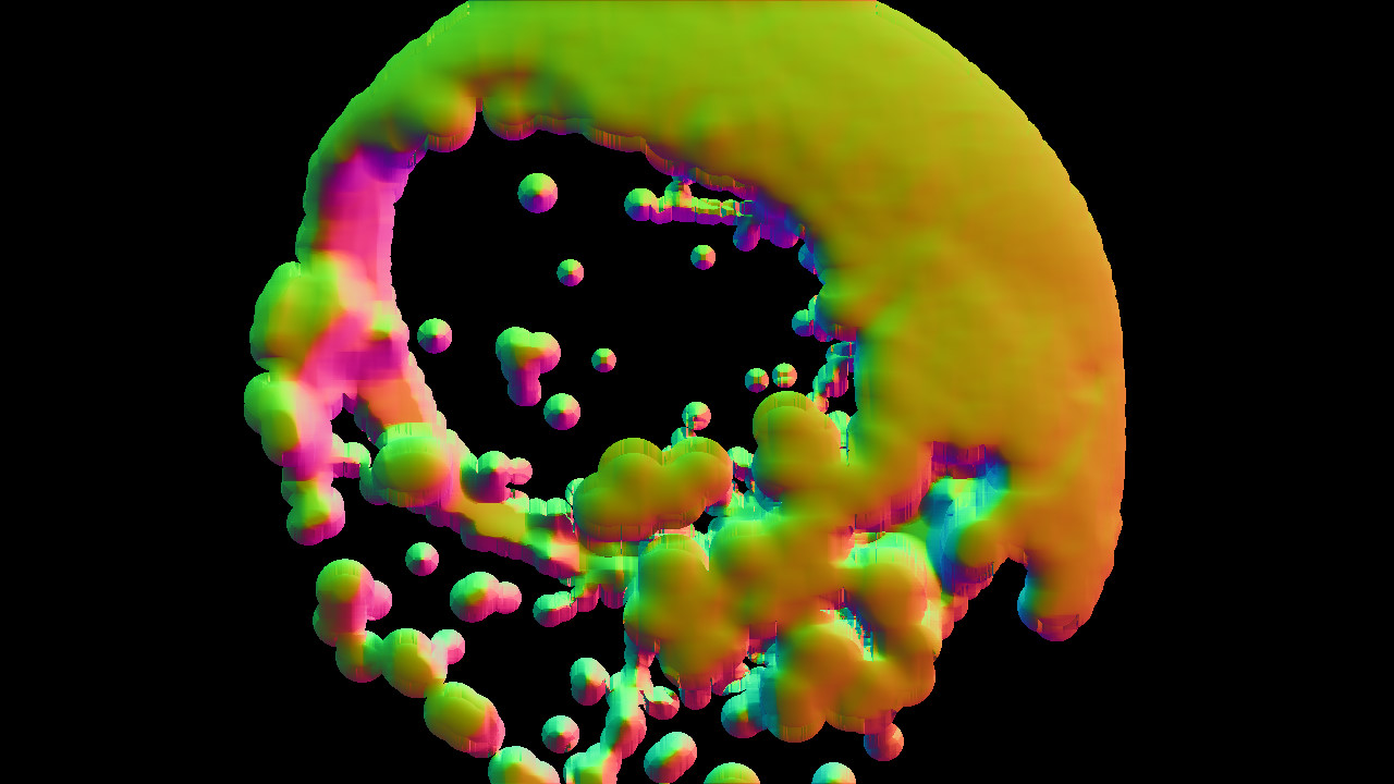
Figure 3.9: Normal image
The depth image and normal image obtained by the calculation so far are written to G-Buffer . By writing just before the rendering pass where the G-Buffer is generated, the geometry based on the calculation result is generated, and shading and lighting are applied.
Excerpt from the code
ScreenSpaceFluidRendering.cs
// --------------------------------------------------------------------
// 4. Write the calculation result to G-Buffer and draw the particles
// --------------------------------------------------------------------
buf.SetGlobalTexture ("_NormalBuffer", normalBufferId); // Set the normal buffer
buf.SetGlobalTexture ("_DepthBuffer", depthBufferId); // Set the depth buffer

// set properties
_renderGBufferMaterial.SetColor("_Diffuse",  _diffuse );
_renderGBufferMaterial.SetColor("_Specular",
  new Vector4(_specular.r, _specular.g, _specular.b, 1.0f - _roughness));
_renderGBufferMaterial.SetColor("_Emission", _emission);

// Set G-Buffer to render target
buf.SetRenderTarget
(
  new RenderTargetIdentifier[4]
  {
    BuiltinRenderTextureType.GBuffer0, // Diffuse
    BuiltinRenderTextureType.GBuffer1, // Specular + Roughness
    BuiltinRenderTextureType.GBuffer2, // World Normal
    BuiltinRenderTextureType.GBuffer3  // Emission
  },
  BuiltinRenderTextureType.CameraTarget  // Depth
);
// Write to G-Buffer
buf.DrawMesh(quad, Matrix4x4.identity, _renderGBufferMaterial);
RenderGBuffer.shader
// GBuffer structure
struct gbufferOut
{
  half4 diffuse: SV_Target0; // Diffuse reflection
  half4 specular: SV_Target1; // specular reflection
  half4 normal: SV_Target2; // normal
  half4 emission: SV_Target3; // emission light
  float depth: SV_Depth; // depth
};

sampler2D _DepthBuffer; // depth
sampler2D _NormalBuffer;// 法線

fixed4 _Diffuse; // Diffuse color
fixed4 _Specular; // Color of specular light
float4 _Emission; // Color of synchrotron radiation

void frag(v2f i, out gbufferOut o)
{
  float2 uv = i.screenPos.xy * 0.5 + 0.5;

  float  d = tex2D(_DepthBuffer,  uv).r;
  float3 n = tex2D(_NormalBuffer, uv).xyz;

#if UNITY_REVERSED_Z
  if (Linear01Depth(d) > 1.0 - 1e-3)
    discard;
#else
  if (Linear01Depth(d) < 1e-3)
    discard;
#endif

  o.diffuse  = _Diffuse;
  o.specular = _Specular;
  o.normal   = float4(n.xyz , 1.0);

  o.emission = _Emission;
#ifndef UNITY_HDR_ON
  o.emission = exp2(-o.emission);
#endif

  o.depth    = d;
}
In the SetRenderTarget method, specify the G-Buffer to be written to the render target . First in the color buffer to be an argument to the target BuiltinRenderTextureType enumeration GBuffer0 , GBuffer1 , GBuffer2 , GBuffer3 specify a RenderTargetIdentifier sequences, also in the depth buffer to be the second argument of the target CameraTarget by specifying a default G- A set of Buffers and depth information can be specified as the render target .
In order to perform calculations on the screen space with a shader that specifies multiple render targets in the command buffer , this is achieved here by using the DrawMesh method to draw a rectangular mesh that covers the screen.
Don't forget to release the temporary RenderTexture generated by the GetTemporaryRT method with the ReleaseTemporaryRT method. If this is not done, memory will be allocated every frame and memory overflow will occur.

Figure 3.10: Rendering result
This chapter focused on manipulating geometry with Deferred Shading . In this sample, as a translucent object, elements such as light absorption according to the thickness, background transmission considering internal refraction, and condensing phenomenon are not implemented. If you want to express it as a liquid, you should implement these elements as well. In order to utilize Deferred Rendering , it is necessary to understand the calculation in 3DCG rendering such as coordinate system, coordinate transformation, shading, lighting, etc. that you do not usually need to be aware of when using Unity. In the range of observation, there are not many sample codes and references for learning using Deferred Rendering in Unity, and I am still not fully understood, but I feel that it is a technology that can expand the range of CG expression. I am. We hope that this chapter will help those who have the purpose of expressing with CG that cannot be realized by conventional Forward Rendering .
http://developer.download.nvidia.com/presentations/2010/gdc/Direct3D_Effects.pdf